
Industry News
Curation by industry experts
Hot Articles
Popular Tags
Injection Molding Void Defects: Causes and Fixes
Why do injection molding void defects deserve early attention?
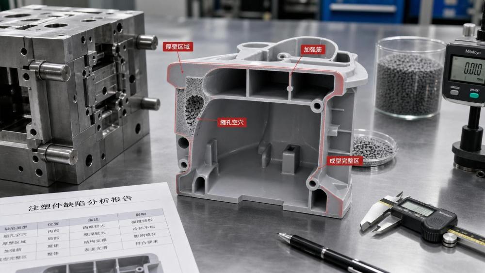
Injection molding void defects are small internal gaps, but their impact is rarely small.
They reduce part density, weaken load zones, and can trigger cosmetic rejects when the surface sinks above the hollow area.
In everyday product categories, that matters more than many teams expect.
A storage lid may lose stiffness, a drinkware handle may crack sooner, and a smart pet feeder housing may fail drop testing.
The problem becomes more serious when parts contact food, water, or repeated thermal cycles.
Void-related weakness does not always appear during basic incoming inspection.
It often shows up later through warpage, assembly instability, or poor field durability.
That is why CHHS regularly treats injection molding void defects as both a quality and sourcing issue.
For molded housewares, bathroom accessories, and daily plastic products, the root cause usually sits between material shrinkage and packing imbalance.
Understanding that interaction makes later corrective decisions much faster.
What exactly causes voids inside a molded part?
The simple explanation is that the outer skin freezes before the inner core finishes shrinking.
When there is not enough pressure-fed material to compensate, a hollow space forms inside.
This is why injection molding void defects are common in thick sections, ribs, bosses, and heavy junctions.
Several process and design factors usually work together:
- Excessive wall thickness that traps heat in the core.
- Low packing pressure or short holding time.
- Early gate freeze that blocks compensation flow.
- High melt temperature that increases shrinkage range.
- Moisture or volatile contamination in sensitive resins.
Need to distinguish voids from bubbles, though.
Gas bubbles come from trapped air, moisture, or degradation gases.
Voids are more often shrinkage-driven and appear in predictable thick areas.
That distinction matters because the fix is different.
Drying a resin may solve bubbles, but it will not fully solve shrinkage-related injection molding void defects.
Which molded products are most vulnerable, and where should you look first?
In practical applications, risk is highest where design thickness changes sharply.
That includes reinforced handles, hinge bases, threaded neck supports, and structural mounting bosses.
Products in the CHHS coverage range show this pattern clearly.
Food-grade PP containers, Tritan bottle caps, bathroom hardware trims, and smart pet device housings often combine cosmetic and structural demands.
That combination makes injection molding void defects harder to accept.
A useful first-pass check is to review these locations:
- Bosses with wall thickness above 60 percent of the nominal wall.
- Rib intersections near the gate or far from the gate.
- Areas under logos, inserts, or decorative textures.
- Parts requiring pressure resistance or repeated latch movement.
When the part is translucent, voids may become visible under backlight.
When the part is opaque, sink marks, poor impact results, or unstable dimensions often provide the first clue.
A quick diagnosis table can prevent the wrong correction
Many teams lose time because they treat every internal cavity as the same defect.
The table below helps separate common signals before changing tools or process windows.
Can process settings alone fix injection molding void defects?
Sometimes yes, but only when the part design still has enough process margin.
If the gate is too small or the section is too heavy, process changes may only reduce the symptom.
They may not eliminate the defect reliably across production shifts.
A sensible adjustment path usually looks like this:
- Increase packing pressure within flash and clamp limits.
- Extend hold time until gate freeze is actually reached.
- Lower melt temperature slightly if the resin allows it.
- Control mold temperature to reduce uneven cooling.
- Confirm cushion stability and shot consistency.
In real production, the hold phase is often underestimated.
A short cycle may look efficient, yet it can lock in higher scrap and hidden field risk.
For daily plastic products, cycle reduction should be judged against defect escape cost, not machine utilization alone.
It is also worth checking whether regrind percentage is affecting shrink behavior.
That is especially relevant for appearance-sensitive consumer items.
When does the real fix require mold or part redesign?
If injection molding void defects keep returning after process tuning, the geometry is usually driving the problem.
The most effective correction is often to remove unnecessary mass from the part.
That may mean coring out a boss, thinning a base, or replacing a solid section with rib support.
Gate strategy matters too.
A gate placed too far from the thick zone can freeze before adequate compensation arrives.
Moving the gate, enlarging it, or changing the runner balance can improve packing efficiency significantly.
Cooling layout is another overlooked factor.
Uneven cooling creates local shrinkage differences that make void formation more likely.
For multi-cavity tools, this can also create cavity-to-cavity variation, which complicates acceptance decisions.
A practical redesign review should ask:
- Can solid features be cored without reducing function?
- Are ribs correctly proportioned to nominal wall thickness?
- Is the gate feeding the last area to freeze?
- Does cooling support balanced shrinkage in critical zones?
How should defect risk be evaluated before approving a supplier or new tool?
The strongest evaluations combine design review, process evidence, and part validation.
A visual sample alone is not enough when injection molding void defects may be internal.
More reliable judgment comes from linking part function to likely defect locations.
For example, a sanitary fitting cover may tolerate a minor hidden void.
A latch body, bottle handle, or motorized pet device bracket may not.
Useful evidence usually includes:
- Part section analysis or CT scans for critical areas.
- Documented molding window with hold pressure and hold time limits.
- Mold flow support for thick sections and gate placement.
- Mechanical validation after cosmetic approval, not before.
- Consistency data across cavities, shifts, and resin lots.
This is where CHHS content can be useful as a reference framework.
It connects molding quality with material safety, consumer use conditions, and mass-production economics.
That broader view matters when a molded component sits inside a food-contact container, bathroom product, or smart household device.
What is the most practical next step if voids are already appearing?
Start by confirming whether the defect is shrinkage void, gas bubble, or both.
After that, map the defect to geometry, gate behavior, and the current packing window.
The fastest progress usually comes from a short, disciplined review rather than broad trial-and-error changes.
Keep the checklist focused:
- Cut or scan samples from the thickest functional zones.
- Compare actual wall sections with nominal design intent.
- Measure gate freeze timing before reducing cycle again.
- Review resin drying, regrind use, and melt history.
- Decide whether the issue is process-correctable or design-limited.
Injection molding void defects rarely come from one isolated parameter.
They usually reflect an imbalance between material shrinkage, part thickness, gate efficiency, and packing control.
Once that balance is visible, corrective action becomes far more predictable.
For ongoing projects, the better path is to set acceptance criteria early, review heavy sections before tooling release, and verify production settings with evidence instead of assumption.
That approach reduces scrap, supports product reliability, and leads to better quality decisions across consumer housewares and light industrial plastic systems.
Recommended News